Electric Outlet Diagram

Wiring Diagram For A Grounded Duplex Receptacle Diy
Wall Outlet Wiring Diagram
Wire An Outlet

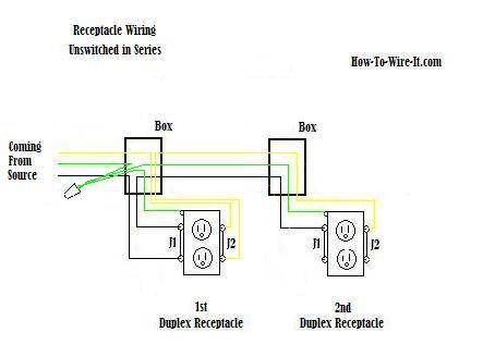
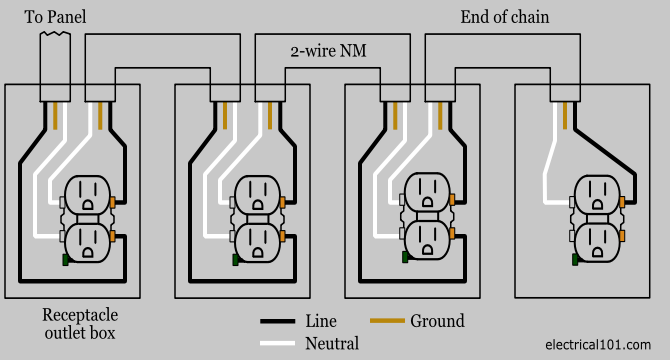
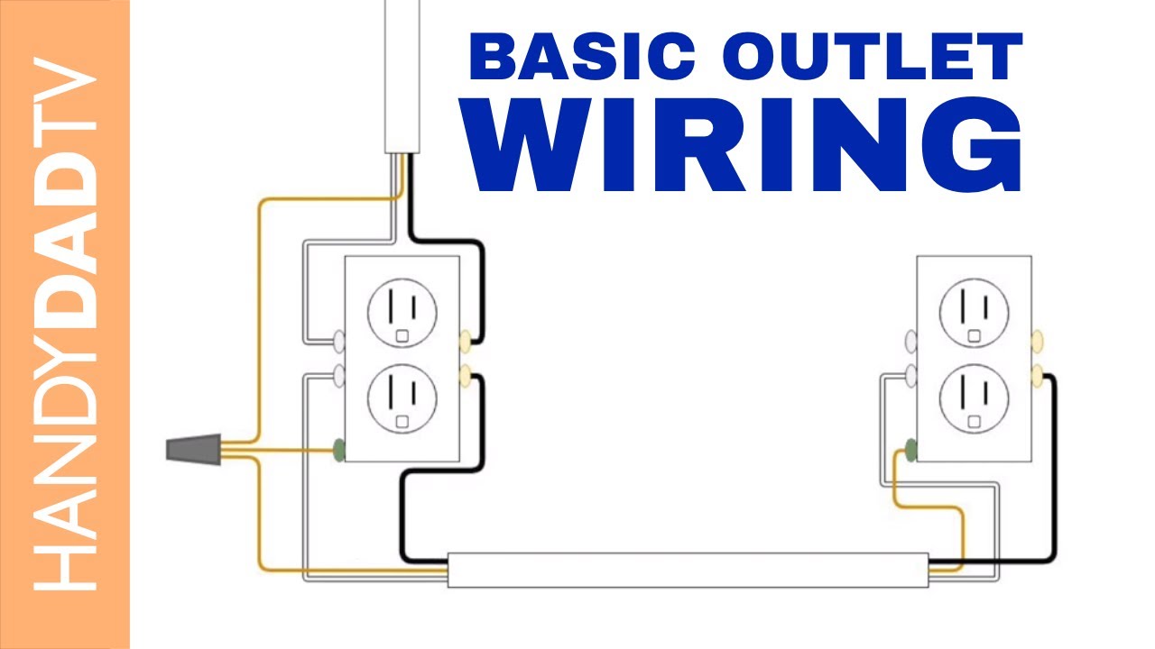
In the diagram below a 2 wire nm cable supplies line voltage from the electrical panel to the first receptacle outlet boxthe black wire line and white neutral connect to the receptacle terminals and another 2 wire nm that travels to the next receptacle.
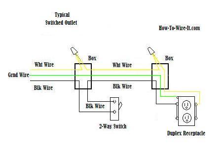
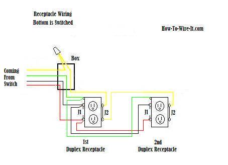
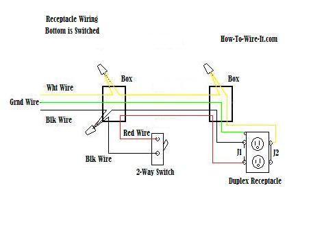
Electric outlet diagram. The diagram below shows the power entering the circuit at the grounded outlet box location then sending power up to the switch and a switched leg back down to the outlet. At the outlets each is wired using a pigtail splice to make the hot and neutral connections. How to wire an electrical outlet wiring diagram wiring an electrical outlet receptacle is quite an easy jobif you are fixing more than one outlet the wiring can be done in parallel or in series. These electrical wiring diagrams show typical connections.
You can use an electrical outlet when. Now some electricians will use a 1wire jumper from the outlet and wire nut together the circuits inside the box but. The neutral wire from the circuit is shared by both sets. Here 3 wire cable is run from a double pole circuit breaker providing an independent 120 volts to two sets of multiple outlets.
Residential electrical wiring diagrams wiring electrical outlets 110 volt outlets 220 volt outlets wiring diagram symbols. This diagram shows the wiring for multiple switched outlets on one switch. The following house electrical wiring diagrams will show almost all the kinds of electrical wiring connections that serve the functions you need at a variety of outlet light and switch boxes. House electrical wiring diagrams.
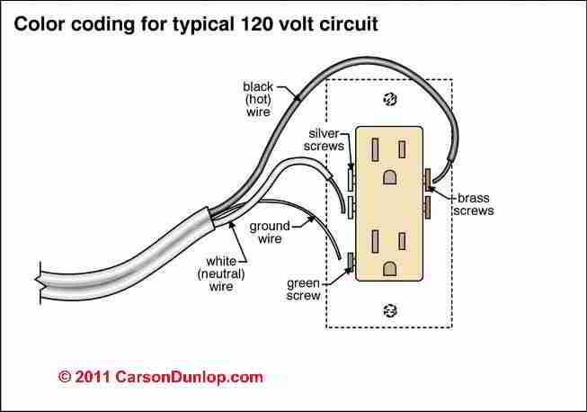
Steps to take when wiring the electrical outletreceptacle. Wiring connections in switch outlet and light boxes. If a switch or outlet is on a circuit that often blows its breaker or fuse dont make matters worse by adding yet another outlet to the circuit. With this wiring both the black and white wires are used to carry 120 volts each and the white wire is wrapped with electrical tape to label it hot.
The diagram above shows 2 outlets wired in series and more outlets can be added to this circuit by wiring the 2nd outlet just like the 1st outlet to keep the circuit continuing on until you end the circuit at the last outlet. Wiring diagram for dual outlets. Wiring diagram for multiple switched outlets. Most arc welders require a dedicated electrical circuit and 220 volt outlet that is sized according to the specifications of the welder as described in further information.
This outlet is commonly used for a heavy load such as a large air conditioner. The source for the circuit is at the switch and 2 wire cable runs to each receptacle outlet. Electrical codes restrict the number of lights or electrical outlets that can be connected to one circuit.

Double Outlet Box Wiring Diagram In The Middle Of A Run In
Wire An Outlet
Wire An Outlet
Wire An Outlet
Outlet Wiring Electrical 101
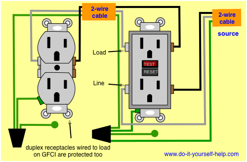
Wiring Diagrams For Electrical Receptacle Outlets Do It
Electrical Outlet Wiring Wiring Schematic Diagram

Electrical Outlet Wiring Wiring Schematic Diagram

110 Receptacle Wiring Wiring Diagram
Electrical Outlet Wiring Wiring Schematic Diagram
Electrical Outlet Wiring Wiring Schematic Diagram
Wall Plug Diagram Wiring Diagram

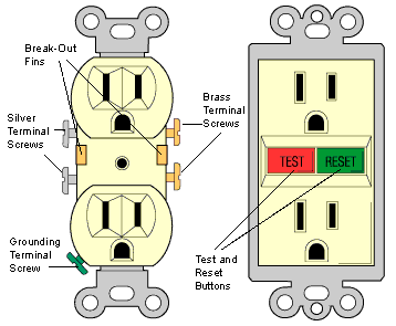
Different Types Of Electrical Outlets And How They Work
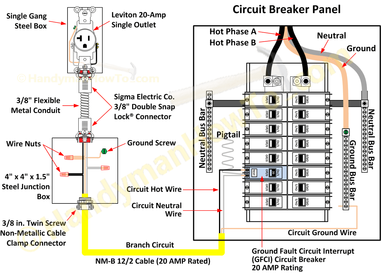
4 Wire Circuit Breaker Diagram Wiring Diagram
4 Wire Circuit Breaker Diagram Wiring Diagram
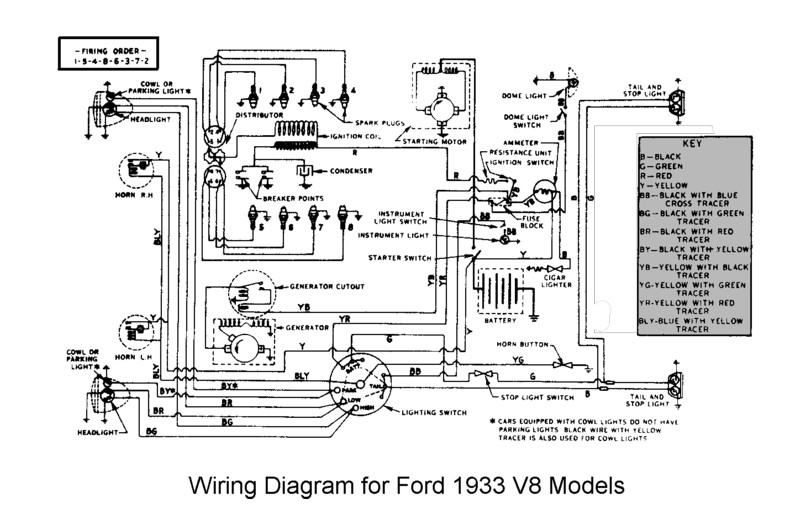
1938 Ford Pickup Coil Wiring Era Electrical Schemes
House Wiring Procedures Wiring Schematic Diagram

Circuits Diagram Ground Wire Wiring Diagram
