Power Plant Logic Diagram

Posted by debyendu chakraborty on monday may 28.
Power plant logic diagram. Latest power plant control system 104 important for safeguarding and protecting the plant from serious damage and is therefore implemented as a digital triple redundant system to ensure the highest standard of reliability. Either discrete controllers located at a central control room or within a central. 3 element drum level control. Plc scada based effective boiler automation system for thermal power plant.
How to commission a thermal power plant. Figure 1 protection engineer. Steam power plant conguration design and control xiao wu1 jiong shen1 yiguo li1 and kwang y. First a brief introduction of ffpp fundamentals and con.
Electrical engineer ht panel inspection testing and commissioning. Browse power plant diagram templates and examples you can make with smartdraw. Various types of master logic diagrams. The steam turbine protection logic is processed in the pcm while the io input and output component.
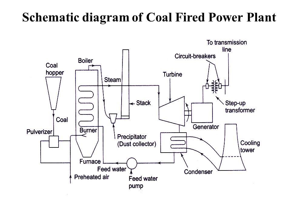
A distributed control system dcs is a computerised control system for a process or plant usually with many control loops in which autonomous controllers are distributed throughout the system but there is no central operator supervisory controlthis is in contrast to systems that use centralized controllers. Create power plant diagram examples like this template called power plant diagram that you can easily edit and customize in minutes. Diagram of a typical coal fired thermal power station. Index terms communication cables programmable logic controller plc power plant supervisory control and data acquisition system scada.
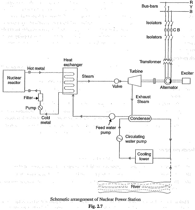
Initiating events of a nuclear power plant being evaluated need to be firstly identified prior to applying probabilistic safety assessment on that plant. The single line diagram sld is the most basic of the set of diagrams that are used to document the electrical functionality of the substation. The control function for process heating ventilation and air conditioning and electrical systems in nuclear power plant npp are represented by control logic diagram. Lee2 this article provides an overview of fossil fuel power plant ffpp congura tion design and especially the control technology both the conventional and the advanced technologies.
Typical diagram of a coal fired thermal power station.


