Mercury Power Trim Wiring Diagram
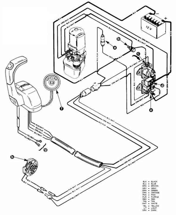
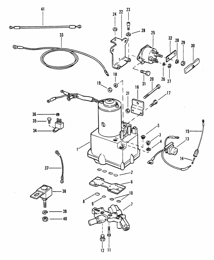
Its electrical sub system consists of a power trim control panel or handle a pump motor and a trim limit switch with connecting wiring.
Mercury power trim wiring diagram. Mercury mariner tilt trim motor diagrams tilttrim replacement parts and repair manuals. Some models may also be equipped with a trim indicator sender. Figure 1 shows a typical system. The hydraulic sub system contains.
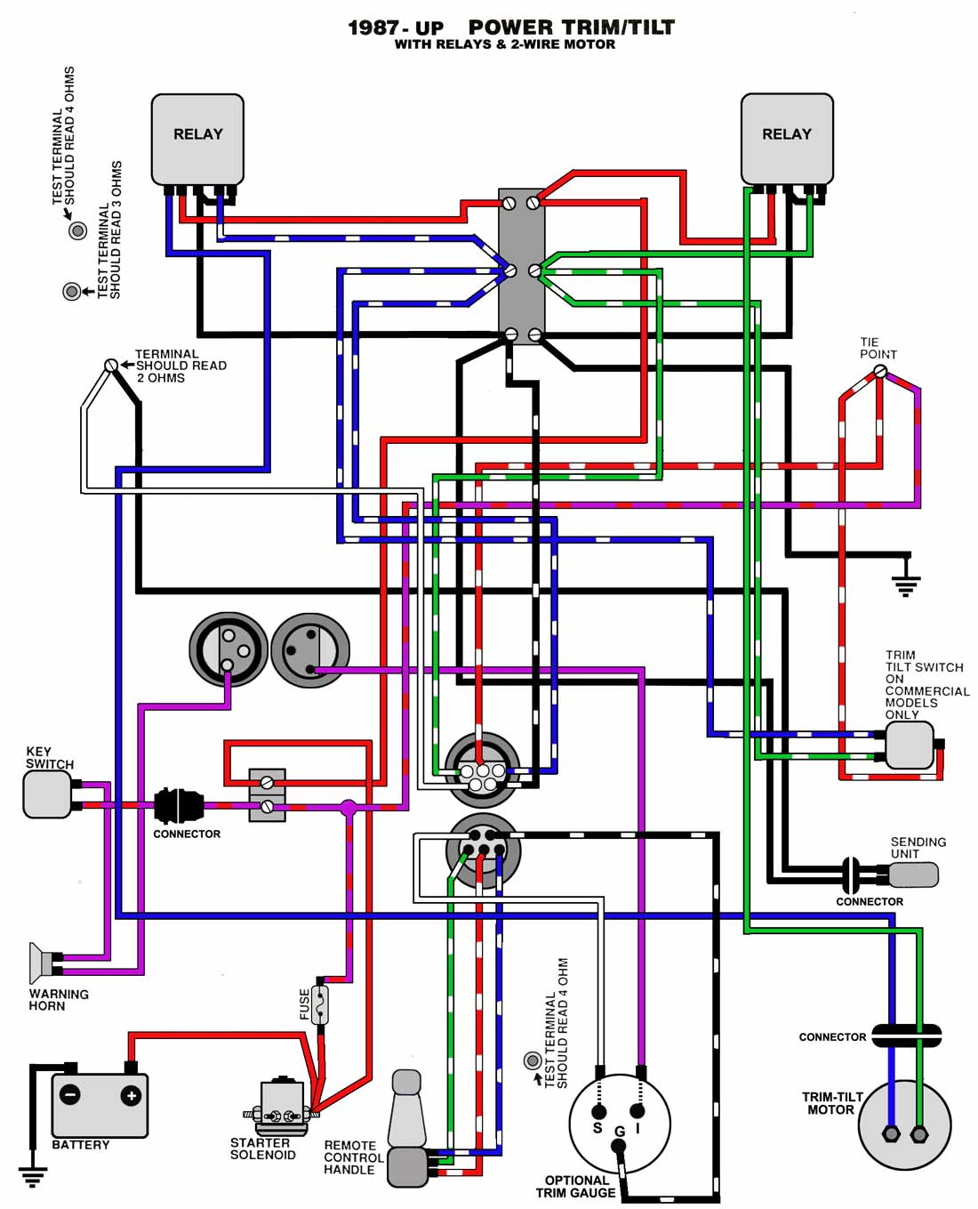
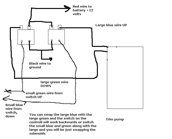
The following power trim system wiring diagram details is for 2001 2002 2003 2004 2005 and 2006 mercruiser 50l 57l and 62l mpi engines. A wiring diagram is a simplified traditional photographic depiction of an electrical circuit. It shows the elements of the circuit as simplified forms and the power and signal connections between the tools. Universal ignition switch wiring diagram page 1 iboats re universal ignition switch wiring diagram you are probably looking at ignition switches for an i o outboard switches require more and different ignition coil troubleshooting tips for mercury mariner mercury mariner ignition coil diagrams coil packs and repair manuals troubleshooting tips.
Mercury outboard ignition switch wiring diagram. Wiring diagrams 475 13 diagram key connectors ground frame ground no connection plugs connection starter relay unit electric starter junction plug battery charging coil electric high pressure fuelpump regulator rectifier batt. Variety of mercury trim motor wiring diagram. 60 fresh mercury outboard power trim wiring diagram images pleasant for you to our blog with this time i am going to show you regarding mercury outboard power trim wiring diagramand today this is actually the very first picture.
This mercruiser power trim and tilt system is electro hydraulically operated. These codes apply to later model motors approximately early 80s to present. Some models may differ.


