Linear Potentiometer Wiring Diagram
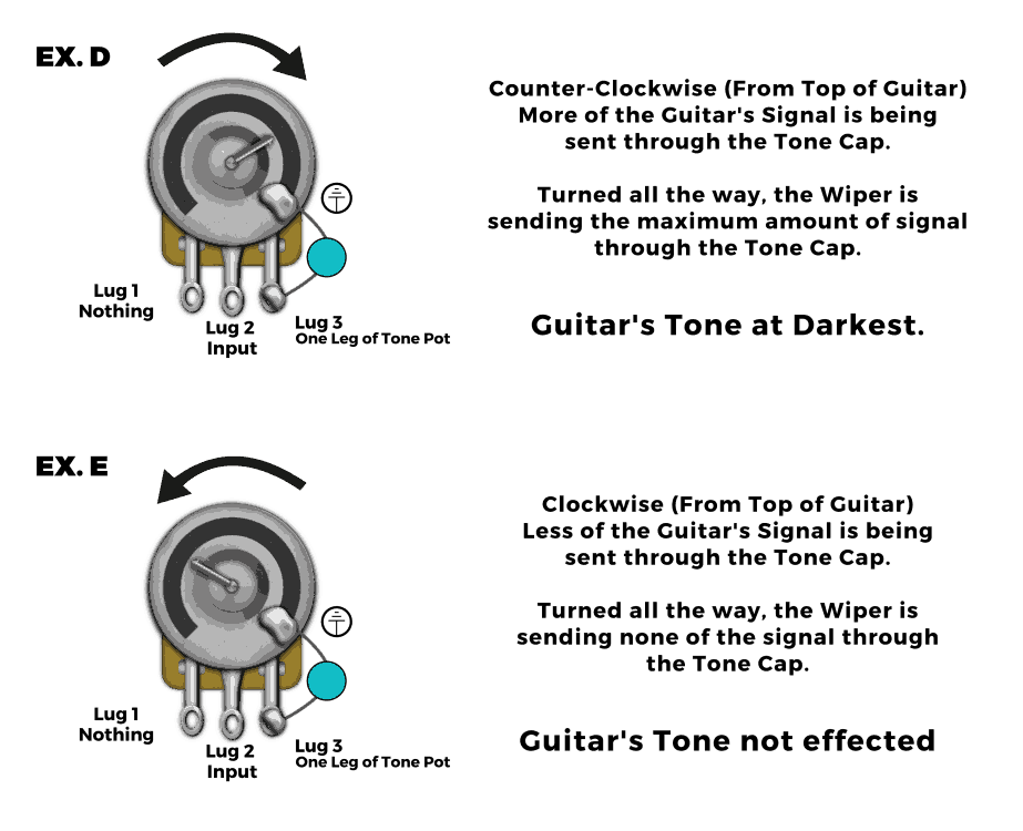
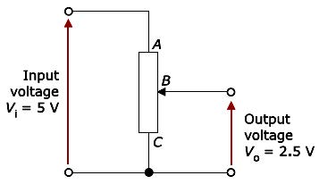
This example uses all three pins of the potentiometer to create a simple way of adjusting the volume of an amplifier.
Linear potentiometer wiring diagram. Skip navigation sign in. This is the basic type of a linear pot. Each component ought to be placed and linked to other parts in specific manner. Learn how to wire a potentiometer.
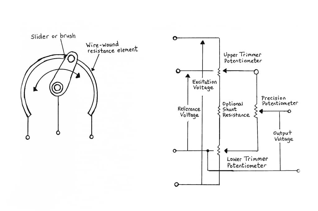
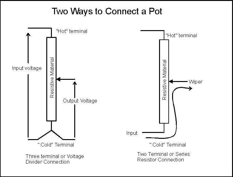
User accessible rotary potentiometers can be fitted with a switch which operates usually at the anti clockwise extreme of rotation. They are further classified into the following types. A potentiometer is a three terminal variable resistor but a rheostat is a two terminal variable resistor. This video is unavailable.
A quick video on how to wire a potentiometer to vary voltage for your project needs. Potentiometer single turn 5 kw linear taper radio shack catalog 271 1714 small hobby motor permanent magnet type radio shack catalog 273 223 or equivalent. A potentiometer can be used as a rheostat but a rheostat cannot be used as a potentiometer. They are also known by the names such as.
Learn how to wire a potentiometer. The more you turn the shaft the more you decrease the volume. For example on a guitar this would be the wire leading away from the pickup. In an integrated amplifier this would be the wire leading from the pre amp stage.
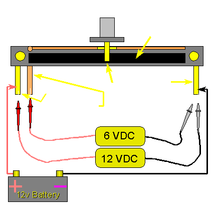
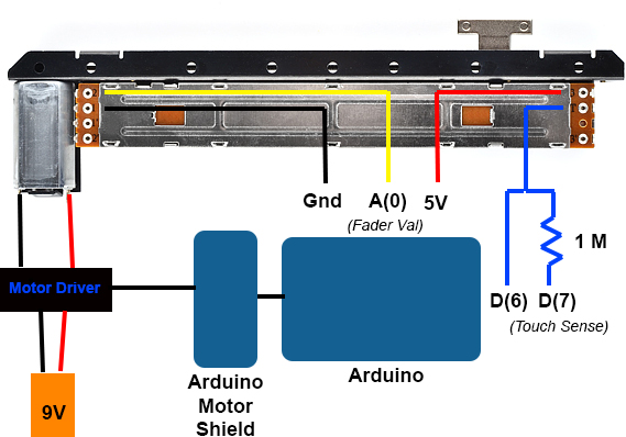
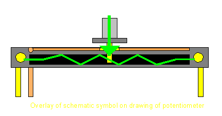
Potentiometer wiring diagram 10k potentiometer wiring diagram dual potentiometer wiring diagram linear potentiometer wiring diagram every electric structure consists of various diverse components. Slider slide pot or fader. Simple motor speed control. The next type of pots is one in which the wiper slides over a straight resistive strip.
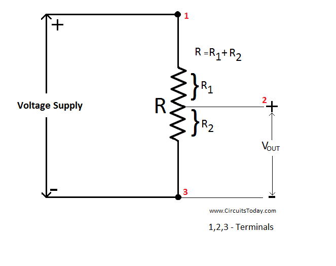
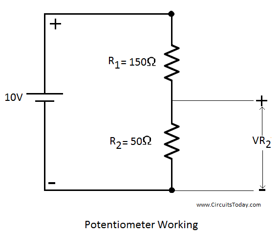
Rheostats potentiometers final demo duration. Learn how to wire a potentiometer. A string potentiometer is a multi turn potentiometer operated by an attached reel of wire turning against a spring enabling it to convert linear position to a variable resistance. By connecting it like this youll get a voltage divider that decreases the voltage of the input signal.
Wiring a potentiometer made simple youtube. Use of voltmeter over ammeter to verify a continuous circuit. Solder this connection as before. Terminal 2 is the input of the potentiometer meaning the output line from the circuit should connect to it.


