Diagram Of Heat Engine
Heat Engines
Heat Engines
Heat Engines And The Second Law

It discusses the concepts.
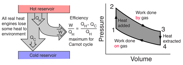
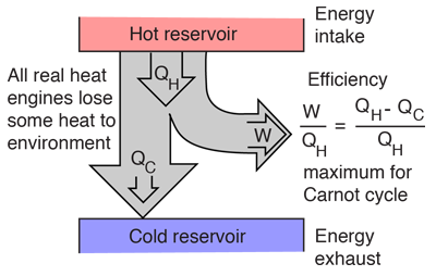
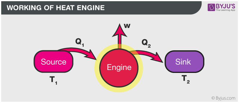
Diagram of heat engine. The figure at right shows a block diagram of a generic heat engine such as the carnot engine. The rest of the heat is removed at a relatively cold temperature qc. The cycle takes place between a hot reservoir at temperature t h and a cold reservoir at temperature t c. In thermodynamics and engineering a heat engine is a system that converts heat or thermal energyand chemical energyto mechanical energy which can then be used to do mechanical work.
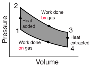
Carnot cycle heat engines maximum efficiency energy flow diagrams thermodynamics physics duration. Heat engines are typically illustrated on a pv diagram heat engines such as automobile engines operate in a cyclic manner adding energy in the form of heat in one part of the cycle and using that energy to do useful work in another part of the cycle. Some of the energy from that input heat is used to perform work w. In the diagram the working body system a term introduced by clausius in 1850 can be any fluid or vapor body through which heat q can be introduced or transmitted to produce work.
The following diagram is a representation of a heat engine showing the energy flow. In a full cycle of a heat engine three things happen. This physics video tutorial provides a basic introduction into heat engines. A carnot cycle acting as a heat engine illustrated on a temperatureentropy diagram.
This physics tutorial video shows you how to solve problems associated with heat engines carnot engines efficiency work heat refrigerators heat pumps and entropy. The organic chemistry tutor 26837 views. This video contains energy flow diagrams that will help you to visualize the transfer of heat energy from the hot reservoir into the heat engine and then to the cold reservoir. This is at a relatively high temperature so the heat can be called qh.
It explains how to calculate the mechanical work performed by a heat engine using heat flowing from the hot reservoir. It does this by bringing a working substance from a higher state temperature to a lower state temperature.

File Schematic Diagram Of A Heat Engine Jpg Wikipedia
Heat Engines
Heat Engines
Heat Engines Converting Heat To Work
Heat Engines

Heat Engine Wikipedia
Heat Engines

Pv Diagrams And Heat Engines

Heat Engine Thermodynamics

Schematic Diagram Of The Stirling Heat Engine Cycle

Applied Physics Tutorial 6

Conceptual Diagrams For A A Conventional Carnot Heat

Carnot Cycle Wikipedia
Heat Engines And The Second Law
Heat Engines
What Is Heat Engine Definition Types Efficiency Derivation

Volcanoes As Heat Engines

Heat Engine Cycle
