Ansi Motor Starter Wiring Diagram
Ansi Motor Starter Wiring Diagram Wiring Diagrams 24

Ansi Motor Starter Wiring Diagram Wiring Diagram

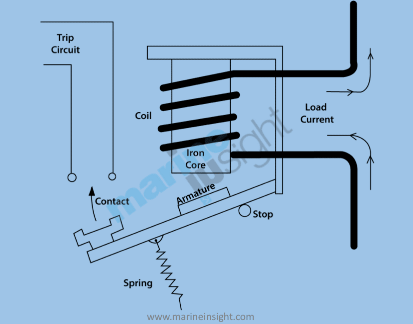
Time Delay Electromechanical Relays Worksheet Digital Circuits

The purpose of this document is to provide a simple cross reference of common schematicwiring diagram symbols used throughout various parts of the world.
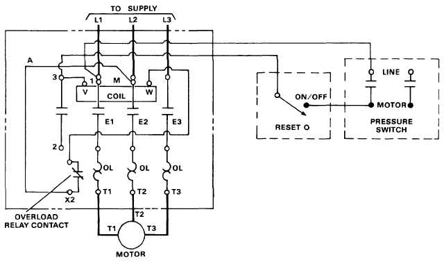
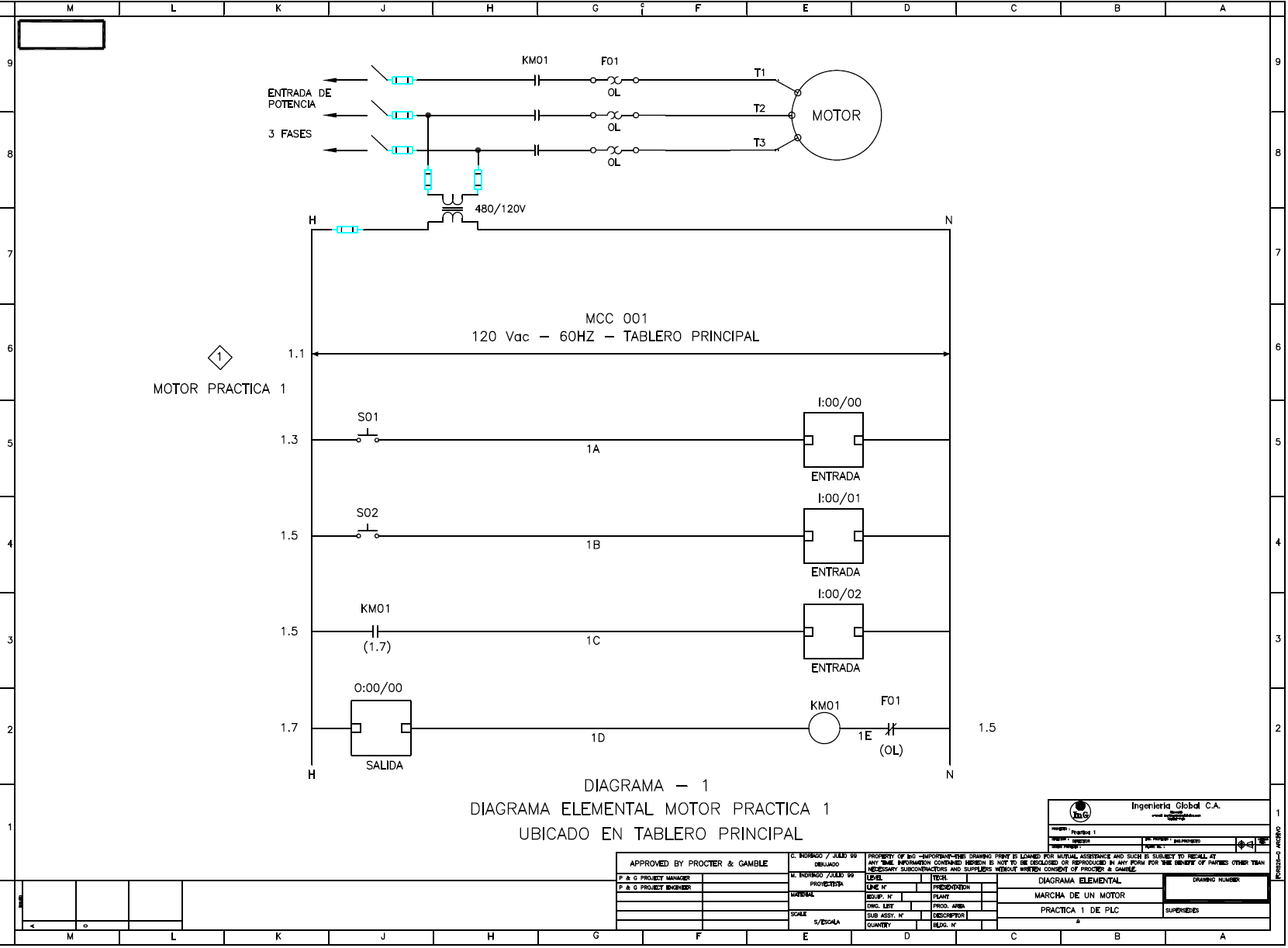
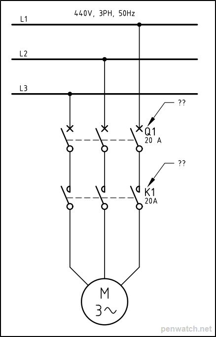
Ansi motor starter wiring diagram. Terminal markings and internal wiring diagrams single phase and polyphase motors meeting nema standards b. 3ph starter3ph motor line voltage control three phase 3ph motor starter controlling a three phase motor rev 08 aug 2006 the above wiring diagram assumes your magnetic starter has a 240v coil. How to wire a contactor and overload. Machine tool or a simple across the line motor starter the need to recognize and understand these.
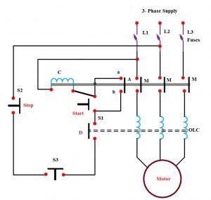
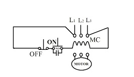
The specific circuit needs to be respectively learned referring to different typical control circuits. These motor starters consist of an on off snap switch combined with a thermal overload device operating on the eutectic alloy ratchet principle. Lever mounted on the front of the switch. How to wire a motor starter.
The technical support page on the automationdirect website is full of valuable information and is available 247. Parts jcxx06p1x xx 3phase starter with startstop button direct online wiring diagram. Wiring diagrams for the various configurations are below. If a single phase motor is single voltage or if either winding is intended for only one voltage the terminal marking shall be determined as follows.
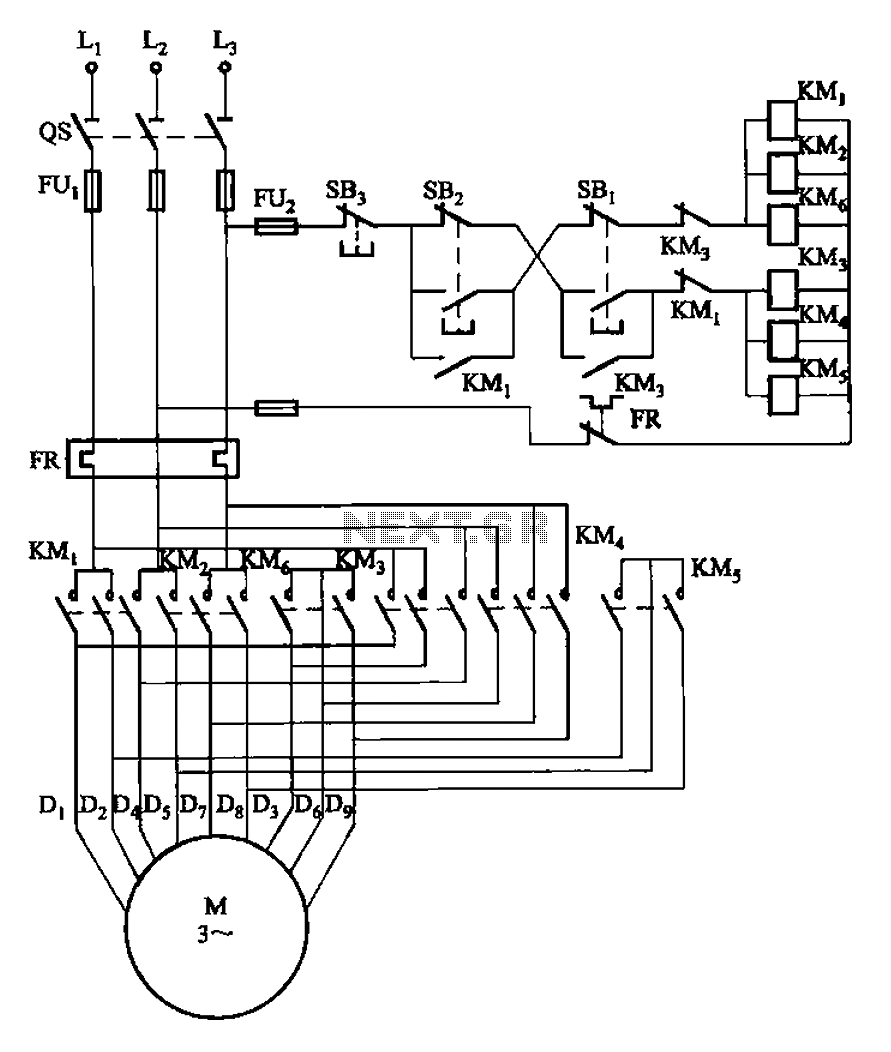
The typical starting system wiring diagrams can divide into non relay control type single starter relay control type and security starter relay control type. Bility of preparing a drafting standard covering electrical schematic wiring and block diagrams for use in the communications electronic electric power indus trial control telephone telegraph and allied industries. Wiring diagrams do not show the operating mechanism since it is not electrically controlled. If you are unsure please feel free to contact us.
If you have a 120v coil instead of running a line from coil overload l2 you must run coil overload neutral. How to wire a contactor and motor protection switch. You must watch this video. Dol motor starter with 230v contactor coil.
The following tables describe the device and show the symbol by area of usage. The following is referenced from the technical and application notes section. The two wire control circuit is shown in figure 2.

Wrg 0626 Ansi Motor Starter Wiring Diagram

Iec Contactor Wiring Diagram Wiring Schematic Diagram

Wrg 5568 Ansi Motor Starter Wiring Diagram
Ansi Wiring Diagram Wiring Diagram Echo
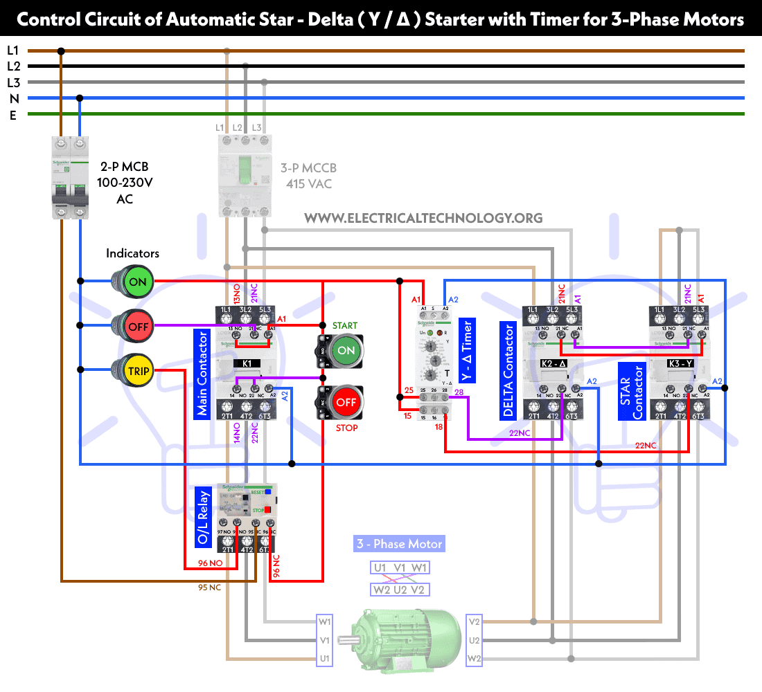
Star Delta Starter Y D Starter Power Control And Wiring

Ab Wire Diagram Wiring Diagram

Electrical And Electronic Drawing Industrial Controls

Iec Contactor Wiring Diagram Wiring Schematic Diagram
Wrg 7916 Ansi Motor Starter Wiring Diagram

1653 Best Electrical Wiring Images In 2019 Electrical
Electrical Drawings Control Real English

Aim Manual Page 54 Single Phase Motors And Controls

Time Delay Electromechanical Relays Worksheet Digital Circuits
Single Phasing In Electrical Motors Causes Effects And

Lighting Contactor Wiring Diagram With Photocell In 2019

Aim Manual Page 54 Single Phase Motors And Controls
Ansi Motor Starter Wiring Diagram Wiring Diagram
Item Designations Or Why Are Relays Called K In
