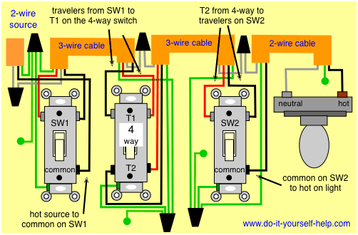
4 Way Light Switch Diagram

Wiring a 4 way switch with light at.
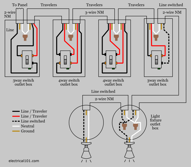
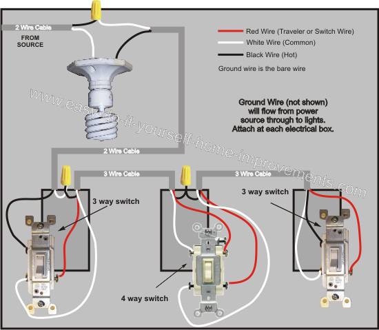
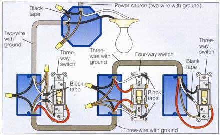
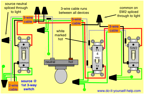
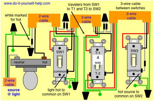
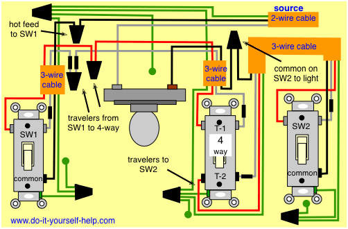
4 way light switch diagram. To view it at full size click on the diagram. How 4 way and 3 way switches work an animation showing how two or three switches can be used to control the same light. The two wiring diagrams above are of a 3 way switch setup and the same basic setup with a 4 way light switch added. For complete instructions on wiring a basic 4 way switch see our wiring a 4 way switch article.
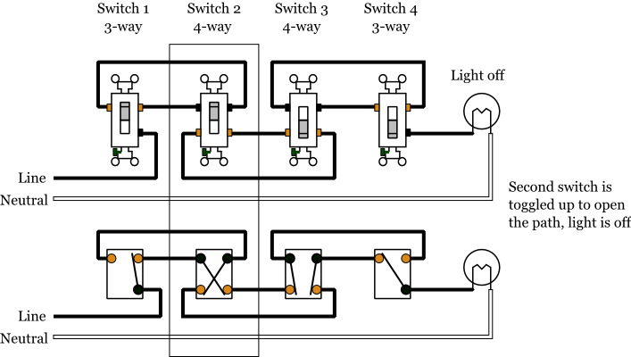
While the physical location of the 4 way switch may be anywhere the electrical location of the switch is always between the two 3 way switches. I have a few of the most common ways in wiring a 4 way switch to help you with your basic home wiring projects. One ground and 4 circuit terminals divided into two matching pairs called travelers. Included are a 4 way dimmer switch diagram and an arrangement that can be used to control room lights from four different locations.
A 4 way switch has five terminals. More about wiring a 4way switch. Each pair of traveler terminals should be wired to the traveler wires from one of the 3 way switches in the circuit. The first switch 3 way travelers brass color connect to one pair of the second switch 4 way travelers black or brass color.
While wiring a 3 way switch is good enough for a staircase or hallway wiring a four way switch is crucial for the addition of a third forth or more switches. This diagram is a thumbnail. A 4 way switch wiring diagram is the clearest and easiest way to wire that pesky 4 way switch. Check here for 4 way switch troubleshooting and help with 3 ways switches here.
A 4 way switch must be wired between two 3 way switches as shown in the diagrams on this page. In the diagrams below the first switch 3 way common terminal connects to line voltage. The white wire becomes the energized switch leg as indicated by using black or red electrical tape. This 4 way switch diagram 2 shows the power source starting at the fixture.
If additional 4 way switches are needed they will also go between the 3 way switches. The white wire of the cable going to the switch is attached to the black line in the fixture box using a wirenut. The switch can be used to control the electricity supplying lights from three locations. How 4 way switches work an animation.
It has 4 terminals or poles and consists of two 3 way switches that are modified. Click here to access note. The 4 way is used when you want to control the light or lights from two or more locations. The center switch is 4 way switch while the outer two switches are 3 way.
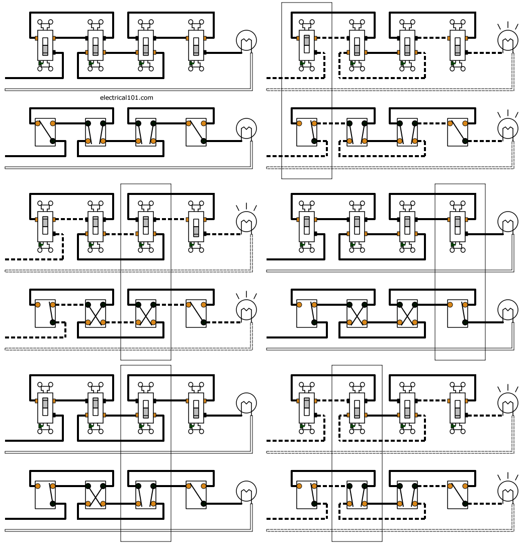
A four switch configuration will have two 3 way switches one on each end and two 4 way switches in the middle. For circuits that control lights from two locations only check the wiring diagrams at this link.
